
Friday, December 12, 2014


Well, here goes!
All in all our group is satisfied with our progress and understanding of the design cycle after this project. We are all too familiar with the idea of designing, building, testing, then redesigning after encountering our many dilemmas. All in all it was educational.
Our prototype, which is more functional apart than it is put together, taught our group the dangers of rapid prototyping. We were under the impression that we had taken all the information we needed from the initial tin can prototype, and as such this would function entirely smoothly.
This was clearly not the case, as we ran into dilemma after dilemma due to poor understanding of our fabrication process. Looking back, it is clear that should we have taken the specifications of the laser and accurately identified the (for lack of a better term) bleed along the edges of each part.
Fortunately for us, this is an acceptable conclusion. The struggles identified above are not ones which will disappear in our engineering careers. There will be more difficult problems and even more frustrating prototypes. Team Ping-Pong Ball Launcher (PPBL) understands that while we may not have a functioning apparatus, we have gained more valuable knowledge of our arduino operations and overall mechanics. We took an idea, made it a design, prototyped, redesigned, and prototyped once more.
Team PPBL is very happy with our achievements, even if they look like a pile of parts with a bad past.
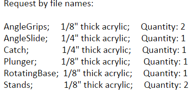
Downloadable Parts, Assembly, and Arduino Code
Angle Grips - https://drive.google.com/file/d/0B5uEqaCyiPVySHljd1lOeThWbzA/view?usp=sharing
Angle Slide - https://drive.google.com/file/d/0B5uEqaCyiPVyY1pZSWREc1U2Z1k/view?usp=sharing
Barrel - https://drive.google.com/file/d/0B5uEqaCyiPVyQmtYbmttV3JCUms/view?usp=sharing
Catch - https://drive.google.com/file/d/0B5uEqaCyiPVyY2pqYkVYaU1MeUE/view?usp=sharing
Plunger - https://drive.google.com/file/d/0B5uEqaCyiPVySVh2NDNKMWNBZ2s/view?usp=sharing
Base - https://drive.google.com/file/d/0B5uEqaCyiPVya3oxR2lxRjhqTDA/view?usp=sharing
Stands - https://drive.google.com/file/d/0B5uEqaCyiPVyOFVkVzBCZk5VNDQ/view?usp=sharing
Assembly - https://drive.google.com/file/d/0B5uEqaCyiPVyWlRyaFdKTEh3eFE/view?usp=sharing
Code **includes all versions, past and present
Stepper 1 - https://drive.google.com/file/d/0B5uEqaCyiPVydXhVaGpNRklyZW8/view?usp=sharing
2 Steppers - https://drive.google.com/file/d/0B5uEqaCyiPVyWEpPeTVpTHJUaU0/view?usp=sharing
Stepper/IR code - https://drive.google.com/file/d/0B5uEqaCyiPVydDhKLXBaY0owRkE/view?usp=sharing
Firing Test
Well.... we thought we solved this problem...


The solution method for now is to try and increase the width of the plunger without adding too much friction or irregularity within the barrel.
Close up Mechanism Adjustments...
Angle Slider
The aftermath of the group trying to use a screw eye in the corrugated cardboard. Clearly it didn't hold.


Entire assembly (servo attached beneath)

Once again the heat tolerance of the acrylic was lower than expected, and as such the diameter is several millimeters too small. We did not compensate enough for this effect, and as such our laser cut plunger still rotates inside the barrel, making some interesting test firing... video coming soon!

Laser Cut/3D Print Results
The laser cutting request was submit this past Tuesday.
Rotating Base
Unfortunately, due to a mix up in orders and limited resources, the group could only use a cardboard specimen of the right dimensions (8" diameter) for the design. This proves to be a key factor in the rest of the development of the project.
Notice the duct tape at the end of the slider... The force in testing was such that it tore through.
Additionally, all screw eyes and brackets are no longer usable as they tear straight through the corrugated cardboard, rendering it relatively useless.
The group will attempt to overcome this through whatever means possible.

The key point of the catch is that the notch cut at its very top is so thin the pins we planned to insert may actually break it in use. We are conducting all tests using duct tape as our new bonding agent, as it seems to be the most reliable and less destructive on our cardboard base. This was unexpected, however, could have been adjusted for with better knowledge of the laser we were using.

The stands are by no means a friction fit in the base, however, they fit well enough such that a bit of mounting clay around the joints has them snug.
Unfortunately, in testing it was found that the cardboard allows too much wiggle room between the notches, and is likely to tear...
Videos of this will be posted soon.

Fortunately, the angle slider worked well!
Until it broke the cardboard base.... and a couple springs.

... Please ignore the extra hole.

... Also the IR remote is working, up and down control the launch angle, left and right control rotation, power raises/lowers the catch.

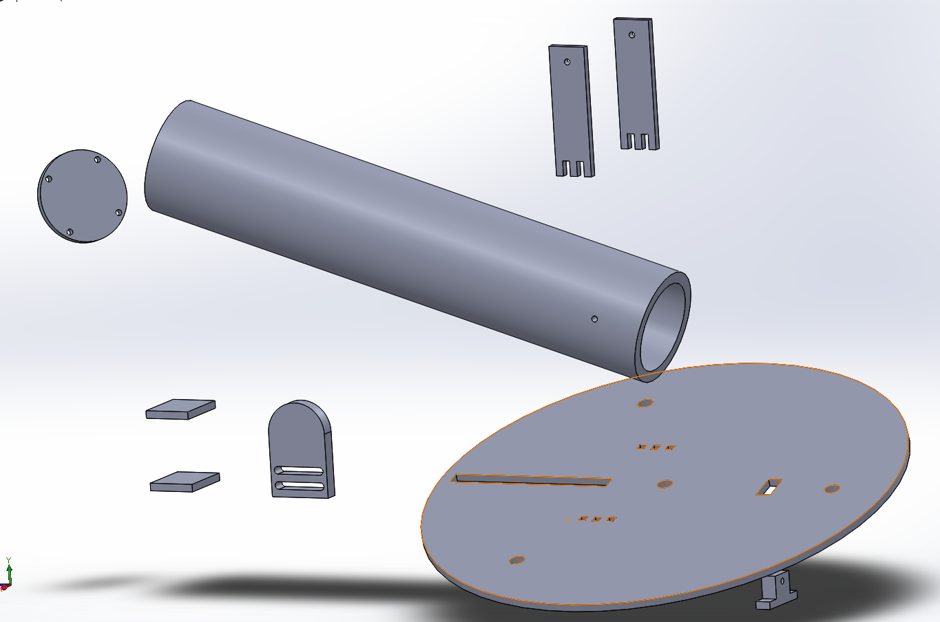
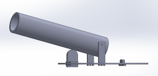
Assembly Motion (video) and Exploded View (pic)
Below are videos of the basic part movement and functionality. By the Solidworks demonstration the design has a fairly large range of firing angles. Each joint is intended to be connected via slots laser cut in mating parts, or pin joints connected by wooden/metal dowels.
This was intentionally designed such that assembly would not prove too difficult. Additionally, the slider beneath the barrel is attached to a spring and stepper motor which is controllable using the IR remote, pictures of which will come later.
The catch is the small mechanism behind the barrel which lowers into the base in order to lock the compressed spring in place until ready to fire. The catch has two springs which set its default position to hidden within the plate. When a servo motor is turned on, the catch raises and allows the stepper motor to begin compressing the spring, or, to release and fire.
Essentially, the controls and operation are as follows:
Hold button on remote to rotate the entire base to the desired angle, and release (via remote and stepper motor).
Adjust the launch angle of the barrel up/down as desired (via remote and stepper motor). - NOTE: this can be done gradually or in several microstep intervals.
Raise the catch. (via a toggle button on the remote and a servo motor).
Load the system by pressing a button to compress the spring and DO NOT RELEASE THE BUTTON. (via remote and another stepper motor).
Lower the catch. (via toggle...) *You may now release the Loading button
Unwind the servo which loads the system. (hold button on the remote until fully unwound).
Raise the catch when ready to fire, via remote.
------
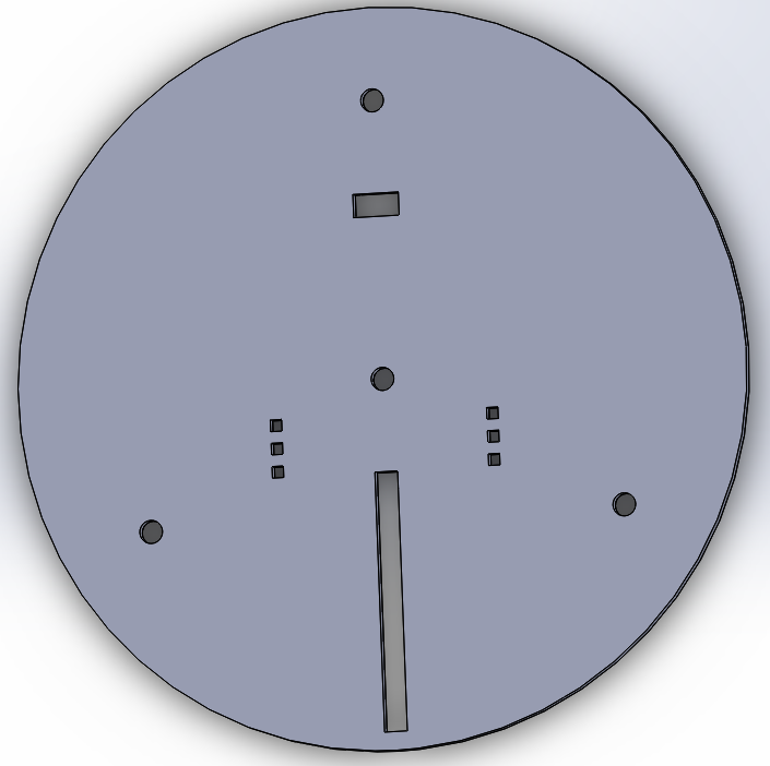
he stepper motors, arduino control board, and servo motor will be mounted to an acrylic rotating base using a drill, screws, and brackets/hinges as necessary. Also, the wheels which allow the base to rotate will slide right in to the 3 equidistant holes about the outside of the base.


This was intentionally designed such that assembly would not prove too difficult. Additionally, the slider beneath the barrel is attached to a spring and stepper motor which is controllable using the IR remote, pictures of which will come later.
The catch is the small mechanism behind the barrel which lowers into the base in order to lock the compressed spring in place until ready to fire. The catch has two springs which set its default position to hidden within the plate. When a servo motor is turned on, the catch raises and allows the stepper motor to begin compressing the spring, or, to release and fire.
Essentially, the controls and operation are as follows:
Hold button on remote to rotate the entire base to the desired angle, and release (via remote and stepper motor).
Adjust the launch angle of the barrel up/down as desired (via remote and stepper motor). - NOTE: this can be done gradually or in several microstep intervals.
Raise the catch. (via a toggle button on the remote and a servo motor).
Load the system by pressing a button to compress the spring and DO NOT RELEASE THE BUTTON. (via remote and another stepper motor).
Lower the catch. (via toggle...) *You may now release the Loading button
Unwind the servo which loads the system. (hold button on the remote until fully unwound).
Raise the catch when ready to fire, via remote.
------
he stepper motors, arduino control board, and servo motor will be mounted to an acrylic rotating base using a drill, screws, and brackets/hinges as necessary. Also, the wheels which allow the base to rotate will slide right in to the 3 equidistant holes about the outside of the base.
Finalized Arduino Code
The first set of code controls two stepper motors via an infra red remote. One compresses the spring, loading the system. The other adjusts the launch angle for the part.
Aaron deciphered the infrared control while Dylan and James fought through the motor coding.
**Libraries are dec
------------
#include <IRremote.h>
#include <IRremoteInt.h>
#include <IRemote.h>
#include <Stepper.h>
int RECV_PIN = 11;
// Remember to add 0x to the hexadecimal codes
long button1 = 0xAC516266;
long button2 = 0xAD5163FB;
l
ong button4 = 0x9FA96F;
IRrecv irrecv(RECV_PIN);
decode_results results;
const int stepsPerRevolution = 200;
Stepper s1(200, 8,9,10,11);
Stepper s2(200, 2,3,4,5);
void setup() { Serial.begin(9600);
irrecv.enableIRIn(); // Start the receiver
irrecv.blink13(true); // blink LED on P13 when IR signal is present
s1.setSpeed(60);
s2.setSpeed(60);
}
void loop()
{
if (irrecv.decode(&results))
{ if (results.value == button1)
{ s1.step(200); delay(500);
}
if (results.value == button2)
{ s1.step(-200); delay(500); }
if (results.value == button3)
{ s2.step(200); delay(500); }
if (results.value == button4)
{ s2.step(-200);
delay(500); }
irrecv.resume(); // Receive the next value
}
}
-------------------------------
The code below controls a servo and stepper motor via an IR remote. The servo is used as a lock/trigger mechanism while the stepper motor is used for the rotating base.
#include <IRremote.h>
#include <IRremoteInt.h>
#include <IRremote.h>
#include <Stepper.h>
#include
int RECV_PIN = 12;
long button1 = 0xAC516266;
long button1a = 0xE516266;
long button2 = 0xAD5163FB;
long button2a =0xAD5163FB;
long button3 = 0xBE15326E;
long button3a = 0xDB9D3097;
long button4 = 0x9FA96F;
long button4a = 0x9912B99A;
long button6 = 0x11;
long button6a = 0x811;
IRrecv irrecv(RECV_PIN);
decode_results results;
const int stepsPerRevolution = 200;
Stepper s1(200, 4,5,6,7);
Stepper s2(200, 8,9,10,11);
Servo myservo;
void setup()
{
Serial.begin(9600);
irrecv.enableIRIn(); // Start the receiver
irrecv.blink13(true); // blink LED on P13 when IR signal is present
s1.setSpeed(60);
s2.setSpeed(60);
myservo.attach(9);
}
void loop()
{ if (irrecv.decode(&results))
{ if (results.value == button1)
{ s1.step(200); delay(100);
} if (results.value == button1a)
{ s1.step(200); delay(100); }
if (results.value == button2)
{
s1.step(-200); delay(100);
}
if (results.value == button2a)
{
s1.step(-200); delay(100);
}
if (results.value == button3)
{
s2.step(200); delay(100);
}
if (results.value == button3a)
{
s2.step(200); delay(100); }
if (results.value == button4)
{
s2.step(-200); delay(100); }
if (results.value == button4a)
{
s2.step(-200); delay(100);
}
if (results.value == button6)
{
myservo.write(0);
delay(100);
}
if (results.value == button6a)
{
myservo.write(90);
delay(100);
}
irrecv.resume(); // Receive the next value
}
}
**Libraries are dec
------------
#include <IRremote.h>
ong button4 = 0x9FA96F;
IRrecv irrecv(RECV_PIN);
decode_results results;
const int stepsPerRevolution = 200;
Stepper s1(200, 8,9,10,11);
Stepper s2(200, 2,3,4,5);
void setup() { Serial.begin(9600);
irrecv.enableIRIn(); // Start the receiver
irrecv.blink13(true); // blink LED on P13 when IR signal is present
s1.setSpeed(60);
s2.setSpeed(60);
}
void loop()
{
if (irrecv.decode(&results))
{ if (results.value == button1)
{ s1.step(200); delay(500);
}
if (results.value == button2)
{ s1.step(-200); delay(500); }
if (results.value == button3)
{ s2.step(200); delay(500); }
if (results.value == button4)
{ s2.step(-200);
delay(500); }
irrecv.resume(); // Receive the next value
}
}
-------------------------------
The code below controls a servo and stepper motor via an IR remote. The servo is used as a lock/trigger mechanism while the stepper motor is used for the rotating base.
#include <IRremote.h>
long button1 = 0xAC516266;
long button1a = 0xE516266;
long button2 = 0xAD5163FB;
long button2a =0xAD5163FB;
long button3 = 0xBE15326E;
long button3a = 0xDB9D3097;
long button4 = 0x9FA96F;
long button4a = 0x9912B99A;
long button6 = 0x11;
long button6a = 0x811;
IRrecv irrecv(RECV_PIN);
decode_results results;
const int stepsPerRevolution = 200;
Stepper s1(200, 4,5,6,7);
Stepper s2(200, 8,9,10,11);
Servo myservo;
void setup()
{
Serial.begin(9600);
irrecv.enableIRIn(); // Start the receiver
irrecv.blink13(true); // blink LED on P13 when IR signal is present
s1.setSpeed(60);
s2.setSpeed(60);
myservo.attach(9);
}
void loop()
{ if (irrecv.decode(&results))
{ if (results.value == button1)
{ s1.step(200); delay(100);
} if (results.value == button1a)
{ s1.step(200); delay(100); }
if (results.value == button2)
{
s1.step(-200); delay(100);
}
if (results.value == button2a)
{
s1.step(-200); delay(100);
}
if (results.value == button3)
{
s2.step(200); delay(100);
}
if (results.value == button3a)
{
s2.step(200); delay(100); }
if (results.value == button4)
{
s2.step(-200); delay(100); }
if (results.value == button4a)
{
s2.step(-200); delay(100);
}
if (results.value == button6)
{
myservo.write(0);
delay(100);
}
if (results.value == button6a)
{
myservo.write(90);
delay(100);
}
irrecv.resume(); // Receive the next value
}
}
Thursday, December 11, 2014
Solidworks Parts/Assembly Pictures
Below are pictures of each Solidworks part as well as the assembly.
Angle Grips
(fit in slow below to hold slide in place)


Angle Grips
(fit in slow below to hold slide in place)

Angle slide
(controls launch angle)

Barrel
(made from 9" pvc pipe)

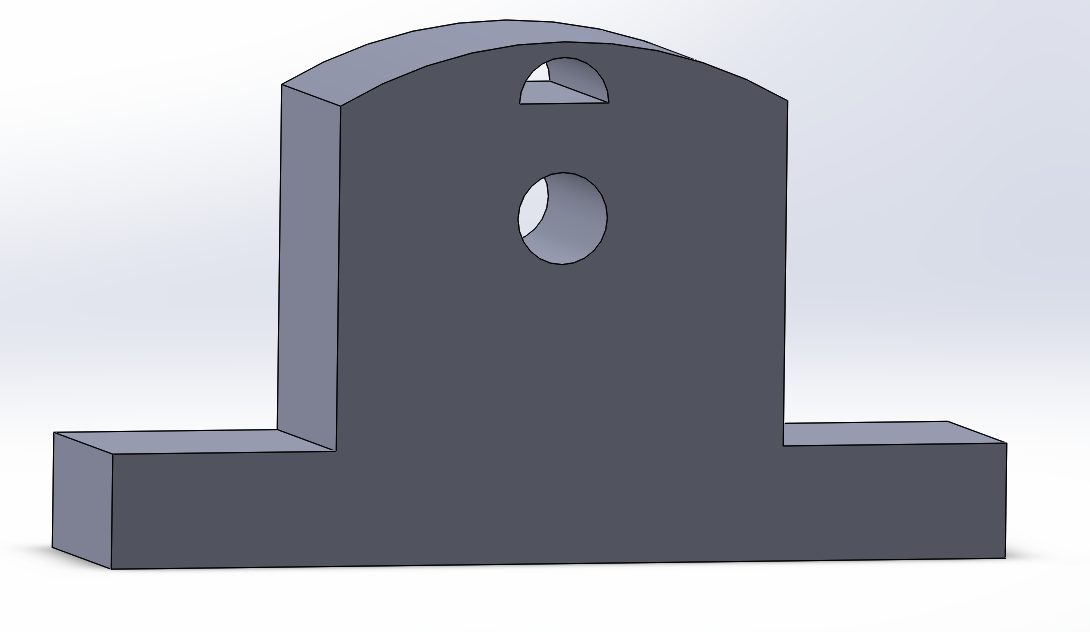
Stand
(mounts barrel to base)

Catch
Plunger

Base
Full Assembly

IR Remote Control Code
*************************************************
#include <IRremote.h>
int RECV_PIN = 11;
int ledBlue = 2;
int ledYellow = 3;
int ledRed = 4;
// Remember to add 0x to the hexadecimal codes
long button1 = 0xAC516266;
long button2 = 0xAD5163FB;
long button3 = 0xBE15326E;
long button4 = 0x9FA96F;
IRrecv irrecv(RECV_PIN);
decode_results results;
void setup()
{
Serial.begin(9600);
pinMode(ledBlue, OUTPUT);
pinMode(ledYellow, OUTPUT);
pinMode(ledRed, OUTPUT);
irrecv.enableIRIn(); // Start the receiver
irrecv.blink13(true); // blink LED on P13 when IR signal is present
}
void loop() {
if (irrecv.decode(&results)) {
if (results.value == button1){digitalWrite(ledBlue, LOW);}
if (results.value == button2){digitalWrite(ledYellow, LOW);}
if (results.value == button3){digitalWrite(ledRed, LOW);}
if (results.value == button4){
digitalWrite(ledBlue, LOW);
delay(10);
digitalWrite(ledBlue, HIGH);
delay(10);
digitalWrite(ledYellow, LOW);
delay(10);
digitalWrite(ledYellow, HIGH);
delay(10);
digitalWrite(ledRed, LOW);
delay(10);
digitalWrite(ledRed, HIGH);
}
irrecv.resume(); // Receive the next value
}
}
**************************************

Tuesday, December 9, 2014
Observations and Changes
The finished prototype serves a great conceptual example for the build. However, the materials we used are clearly far from ideal and so the functionality isn't there.
The launch platform inside the barrel spins since it is only restrained at two points and the spring is not thick enough to fill the inside of the barrel.To fix this, the final tube will be 1.5" inner diameter pvc pipe with a 3/4" compression spring. This is a tighter fit than the 2.5" can here.
Also, the fishing line will be connected to the launch platform at 4 points, every 90 degrees along the outside. This should eliminate any unwanted rotation inside the barrel. These four cords meet at the center of the spring and connect to an individual string which runs along the barrel and out the end cap. This string then moves through a track of eye-hooks which lead to a stepper motor, which compresses the spring. This component is referred to as the loading mechanism.
The string will run through a catch that is pulled into the base, in order to keep the spring compressed. The loading mechanism stepper motor then unwinds, preparing the launcher for firing. The catch is then lifted by a servo motor, releasing the compressed spring, propelling the launch platform, and firing the ping pong ball.
For this purpose the group decided that to make more room for the loading mechanism on the base plate. The entire cannon will be shifted several inches farther from the center of the base disc.
Also, the entire apparatus will be held up by 3 wheels along the outside of the base. At the center of the base is another servo which should allow for free 360 degree rotation.
Sunday, December 7, 2014
Prototype with Adjustable Launch Angle
These pictures show the basic function of the launch angle disc in action.


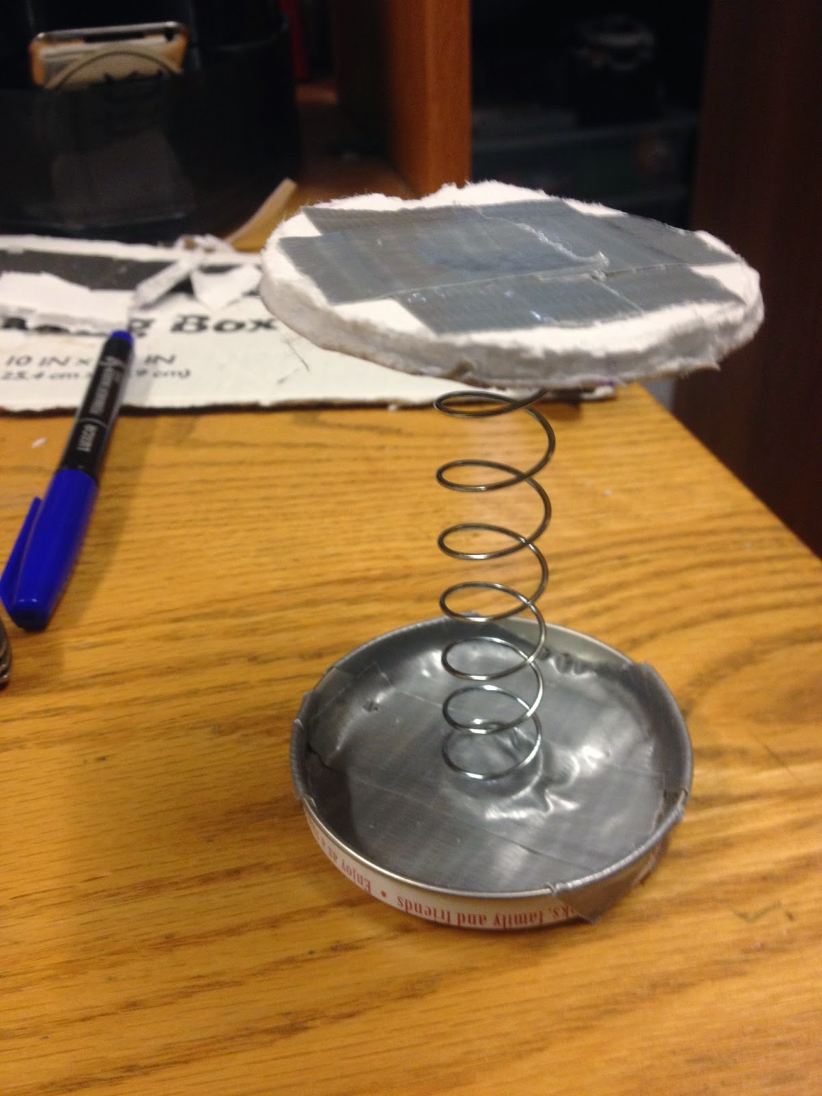
Rotating Base, Launch Angle Track, Compression Spring
The group met today and made a prototype/proof of concept we're happy with. Also posted are components of the base.
The second picture shows a track for a circular component which controls the launch angle by physically pushing the barrel itself.
Additionally,the inner components of the barrel include a secured compression spring and launch platform.
Materials : foam core, spring, duct tape. aluminum can, bolt, thin aluminum rod


Thursday, December 4, 2014
Wednesday, November 19, 2014

Tuesday, November 18, 2014
Big Changes

We decided to switch from our etchasketch idea to a ping pong ball cannon! Here are the first few sketches we designed. Essentially, our goal is to create a platform inside a barrel which can be automatically compressed and released by an arduino control board and several motors. This will propel the ping pong ball.
Additionally, we would like to account for an adjustable launch angle (which may be done using a rotating egg shaped mechanism), as well as a rotating base.
New Team Name: Team Ping-Pong Ball Launcher (PPBL)
Thursday, November 13, 2014
RC Controller
I managed to pop open an old RC car from home. Now we've got a Radio transmitter/receiver to work with, a battery pack, and some servo motors.
The original controller has controls for each individual motor as well as a button which moves both at once.
Maybe a similar configuration could be used in order to make diagonal lines?
*I've also opened up the controller now, and there is an antenna for increased range.
Tuesday, November 4, 2014
Team Name: DJA arduino etchaskech
Our goal is to create an arduino controlled device to move a head in 2 dimensions, in order to create drawings. Create a manual as well as a code bases control interface. Hopefully create some preloaded drawings using the code based control interface.
This is to satisfy the Mechanical Design Lab I requirement, given the instruction to "make something that moves" and to have a good time doing it.

This video shows a simalar type of machine but moving the bases instead on the head.
Our goal is to create an arduino controlled device to move a head in 2 dimensions, in order to create drawings. Create a manual as well as a code bases control interface. Hopefully create some preloaded drawings using the code based control interface.
This is to satisfy the Mechanical Design Lab I requirement, given the instruction to "make something that moves" and to have a good time doing it.
Team Picture
This video shows a simalar type of machine but moving the bases instead on the head.
Subscribe to:
Comments (Atom)