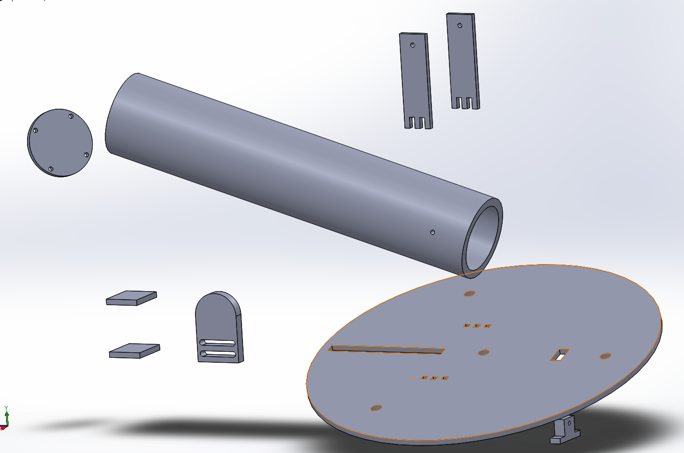
This was intentionally designed such that assembly would not prove too difficult. Additionally, the slider beneath the barrel is attached to a spring and stepper motor which is controllable using the IR remote, pictures of which will come later.
The catch is the small mechanism behind the barrel which lowers into the base in order to lock the compressed spring in place until ready to fire. The catch has two springs which set its default position to hidden within the plate. When a servo motor is turned on, the catch raises and allows the stepper motor to begin compressing the spring, or, to release and fire.
Essentially, the controls and operation are as follows:
Hold button on remote to rotate the entire base to the desired angle, and release (via remote and stepper motor).
Adjust the launch angle of the barrel up/down as desired (via remote and stepper motor). - NOTE: this can be done gradually or in several microstep intervals.
Raise the catch. (via a toggle button on the remote and a servo motor).
Load the system by pressing a button to compress the spring and DO NOT RELEASE THE BUTTON. (via remote and another stepper motor).
Lower the catch. (via toggle...) *You may now release the Loading button
Unwind the servo which loads the system. (hold button on the remote until fully unwound).
Raise the catch when ready to fire, via remote.
------
he stepper motors, arduino control board, and servo motor will be mounted to an acrylic rotating base using a drill, screws, and brackets/hinges as necessary. Also, the wheels which allow the base to rotate will slide right in to the 3 equidistant holes about the outside of the base.


No comments:
Post a Comment