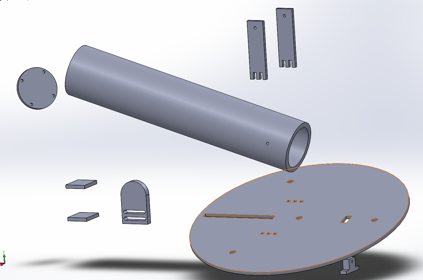
Below are videos of the basic part movement and functionality. By the Solidworks demonstration the design has a fairly large range of firing angles. Each joint is intended to be connected via slots laser cut in mating parts, or pin joints connected by wooden/metal dowels.
This was intentionally designed such that assembly would not prove too difficult.
Additionally, the slider beneath the barrel is attached to a spring and stepper motor which is controllable using the IR remote, pictures of which will come later.
The catch is the small mechanism behind the barrel which lowers into the base in order to lock the compressed spring in place until ready to fire. The catch has two springs which set its default position to hidden within the plate. When a servo motor is turned on, the catch raises and allows the stepper motor to begin compressing the spring, or, to release and fire.
Essentially, the controls and operation are as follows:
Hold button on remote to rotate the entire base to the desired angle, and release (via remote and stepper motor).
Adjust the launch angle of the barrel up/down as desired (via remote and stepper motor). - NOTE: this can be done gradually or in several microstep intervals.
Raise the catch. (via a toggle button on the remote and a servo motor).
Load the system by pressing a button to compress the spring and DO NOT RELEASE THE BUTTON. (via remote and another stepper motor).
Lower the catch. (via toggle...) *You may now release the Loading button
Unwind the servo which loads the system. (hold button on the remote until fully unwound).
Raise the catch when ready to fire, via remote.
------
he stepper motors, arduino control board, and servo motor will be mounted to an acrylic rotating base using a drill, screws, and brackets/hinges as necessary.
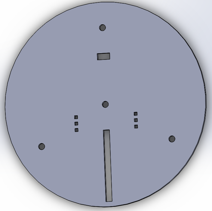
Also, the wheels which allow the base to rotate will slide right in to the 3 equidistant holes about the outside of the base.
Friday, December 12, 2014
Finalized Arduino Code
The first set of code controls two stepper motors via an infra red remote. One compresses the spring, loading the system. The other adjusts the launch angle for the part.
Aaron deciphered the infrared control while Dylan and James fought through the motor coding.
**Libraries are dec
------------
#include <IRremote.h>
#include <IRremoteInt.h>
#include <IRemote.h>
#include <Stepper.h>
int RECV_PIN = 11;
// Remember to add 0x to the hexadecimal codes
long button1 = 0xAC516266;
long button2 = 0xAD5163FB;
l ong button3 = 0xBE15326E;
ong button4 = 0x9FA96F;
IRrecv irrecv(RECV_PIN);
decode_results results;
const int stepsPerRevolution = 200;
Stepper s1(200, 8,9,10,11);
Stepper s2(200, 2,3,4,5);
void setup() { Serial.begin(9600);
irrecv.enableIRIn(); // Start the receiver
irrecv.blink13(true); // blink LED on P13 when IR signal is present
s1.setSpeed(60);
s2.setSpeed(60);
}
void loop()
{
if (irrecv.decode(&results))
{ if (results.value == button1)
{ s1.step(200); delay(500);
}
if (results.value == button2)
{ s1.step(-200); delay(500); }
if (results.value == button3)
{ s2.step(200); delay(500); }
if (results.value == button4)
{ s2.step(-200);
delay(500); }
irrecv.resume(); // Receive the next value
}
}
-------------------------------
The code below controls a servo and stepper motor via an IR remote. The servo is used as a lock/trigger mechanism while the stepper motor is used for the rotating base.
#include <IRremote.h>
#include <IRremoteInt.h>
#include <IRremote.h>
#include <Stepper.h>
#include
int RECV_PIN = 12; // Remember to add 0x to the hexadecimal codes
long button1 = 0xAC516266;
long button1a = 0xE516266;
long button2 = 0xAD5163FB;
long button2a =0xAD5163FB;
long button3 = 0xBE15326E;
long button3a = 0xDB9D3097;
long button4 = 0x9FA96F;
long button4a = 0x9912B99A;
long button6 = 0x11;
long button6a = 0x811;
IRrecv irrecv(RECV_PIN);
decode_results results;
const int stepsPerRevolution = 200;
Stepper s1(200, 4,5,6,7);
Stepper s2(200, 8,9,10,11);
Servo myservo;
void setup()
{
Serial.begin(9600);
irrecv.enableIRIn(); // Start the receiver
irrecv.blink13(true); // blink LED on P13 when IR signal is present
s1.setSpeed(60);
s2.setSpeed(60);
myservo.attach(9);
}
void loop()
{ if (irrecv.decode(&results))
{ if (results.value == button1)
{ s1.step(200); delay(100);
} if (results.value == button1a)
{ s1.step(200); delay(100); }
if (results.value == button2)
{
s1.step(-200); delay(100);
}
if (results.value == button2a)
{
s1.step(-200); delay(100);
}
if (results.value == button3)
{
s2.step(200); delay(100);
}
if (results.value == button3a)
{
s2.step(200); delay(100); }
if (results.value == button4)
{
s2.step(-200); delay(100); }
if (results.value == button4a)
{
s2.step(-200); delay(100);
}
if (results.value == button6)
{
myservo.write(0);
delay(100);
}
if (results.value == button6a)
{
myservo.write(90);
delay(100);
}
irrecv.resume(); // Receive the next value
}
}
**Libraries are dec
------------
#include <IRremote.h>
ong button4 = 0x9FA96F;
IRrecv irrecv(RECV_PIN);
decode_results results;
const int stepsPerRevolution = 200;
Stepper s1(200, 8,9,10,11);
Stepper s2(200, 2,3,4,5);
void setup() { Serial.begin(9600);
irrecv.enableIRIn(); // Start the receiver
irrecv.blink13(true); // blink LED on P13 when IR signal is present
s1.setSpeed(60);
s2.setSpeed(60);
}
void loop()
{
if (irrecv.decode(&results))
{ if (results.value == button1)
{ s1.step(200); delay(500);
}
if (results.value == button2)
{ s1.step(-200); delay(500); }
if (results.value == button3)
{ s2.step(200); delay(500); }
if (results.value == button4)
{ s2.step(-200);
delay(500); }
irrecv.resume(); // Receive the next value
}
}
-------------------------------
The code below controls a servo and stepper motor via an IR remote. The servo is used as a lock/trigger mechanism while the stepper motor is used for the rotating base.
#include <IRremote.h>
long button1 = 0xAC516266;
long button1a = 0xE516266;
long button2 = 0xAD5163FB;
long button2a =0xAD5163FB;
long button3 = 0xBE15326E;
long button3a = 0xDB9D3097;
long button4 = 0x9FA96F;
long button4a = 0x9912B99A;
long button6 = 0x11;
long button6a = 0x811;
IRrecv irrecv(RECV_PIN);
decode_results results;
const int stepsPerRevolution = 200;
Stepper s1(200, 4,5,6,7);
Stepper s2(200, 8,9,10,11);
Servo myservo;
void setup()
{
Serial.begin(9600);
irrecv.enableIRIn(); // Start the receiver
irrecv.blink13(true); // blink LED on P13 when IR signal is present
s1.setSpeed(60);
s2.setSpeed(60);
myservo.attach(9);
}
void loop()
{ if (irrecv.decode(&results))
{ if (results.value == button1)
{ s1.step(200); delay(100);
} if (results.value == button1a)
{ s1.step(200); delay(100); }
if (results.value == button2)
{
s1.step(-200); delay(100);
}
if (results.value == button2a)
{
s1.step(-200); delay(100);
}
if (results.value == button3)
{
s2.step(200); delay(100);
}
if (results.value == button3a)
{
s2.step(200); delay(100); }
if (results.value == button4)
{
s2.step(-200); delay(100); }
if (results.value == button4a)
{
s2.step(-200); delay(100);
}
if (results.value == button6)
{
myservo.write(0);
delay(100);
}
if (results.value == button6a)
{
myservo.write(90);
delay(100);
}
irrecv.resume(); // Receive the next value
}
}
Thursday, December 11, 2014
Solidworks Parts/Assembly Pictures
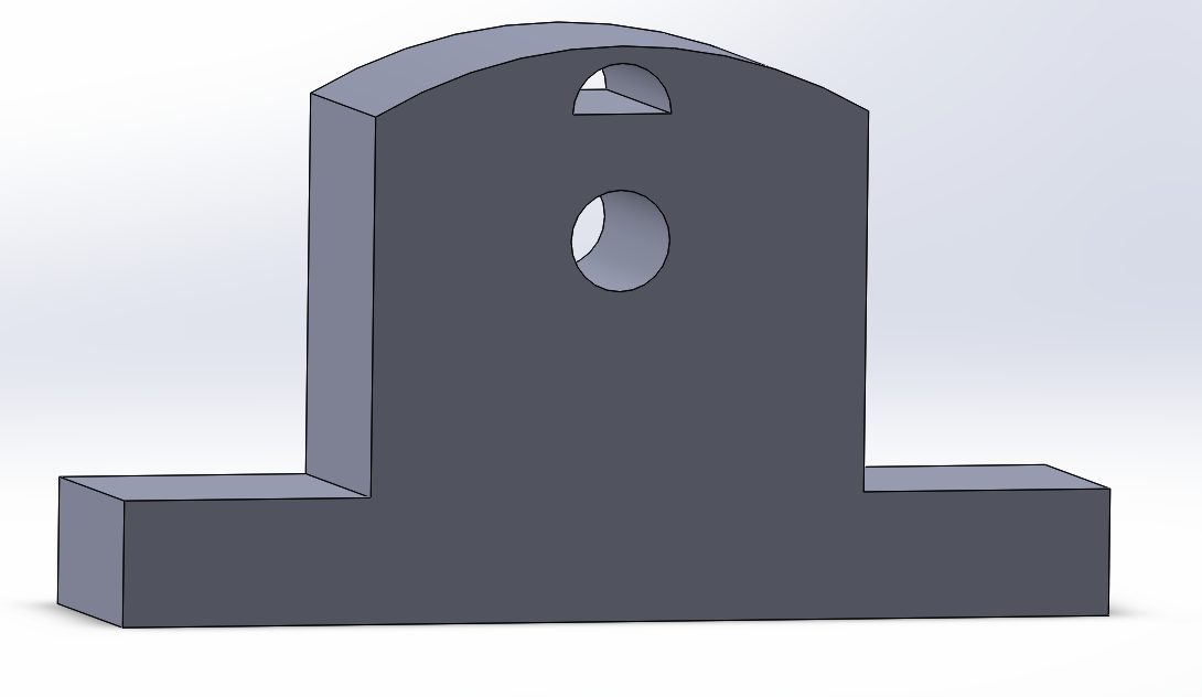
Below are pictures of each Solidworks part as well as the assembly.
Angle Grips
(fit in slow below to hold slide in place)
Angle Grips
(fit in slow below to hold slide in place)
Angle slide
(controls launch angle)
Barrel
(made from 9" pvc pipe)
Stand
(mounts barrel to base)
Catch
Plunger
Base
Full Assembly
IR Remote Control Code
*************************************************
#include <IRremote.h>
int RECV_PIN = 11;
int ledBlue = 2;
int ledYellow = 3;
int ledRed = 4;
// Remember to add 0x to the hexadecimal codes
long button1 = 0xAC516266;
long button2 = 0xAD5163FB;
long button3 = 0xBE15326E;
long button4 = 0x9FA96F;
IRrecv irrecv(RECV_PIN);
decode_results results;
void setup()
{
Serial.begin(9600);
pinMode(ledBlue, OUTPUT);
pinMode(ledYellow, OUTPUT);
pinMode(ledRed, OUTPUT);
irrecv.enableIRIn(); // Start the receiver
irrecv.blink13(true); // blink LED on P13 when IR signal is present
}
void loop() {
if (irrecv.decode(&results)) {
if (results.value == button1){digitalWrite(ledBlue, LOW);}
if (results.value == button2){digitalWrite(ledYellow, LOW);}
if (results.value == button3){digitalWrite(ledRed, LOW);}
if (results.value == button4){
digitalWrite(ledBlue, LOW);
delay(10);
digitalWrite(ledBlue, HIGH);
delay(10);
digitalWrite(ledYellow, LOW);
delay(10);
digitalWrite(ledYellow, HIGH);
delay(10);
digitalWrite(ledRed, LOW);
delay(10);
digitalWrite(ledRed, HIGH);
}
irrecv.resume(); // Receive the next value
}
}
**************************************
#include <IRremote.h>
int RECV_PIN = 11;
int ledBlue = 2;
int ledYellow = 3;
int ledRed = 4;
// Remember to add 0x to the hexadecimal codes
long button1 = 0xAC516266;
long button2 = 0xAD5163FB;
long button3 = 0xBE15326E;
long button4 = 0x9FA96F;
IRrecv irrecv(RECV_PIN);
decode_results results;
void setup()
{
Serial.begin(9600);
pinMode(ledBlue, OUTPUT);
pinMode(ledYellow, OUTPUT);
pinMode(ledRed, OUTPUT);
irrecv.enableIRIn(); // Start the receiver
irrecv.blink13(true); // blink LED on P13 when IR signal is present
}
void loop() {
if (irrecv.decode(&results)) {
if (results.value == button1){digitalWrite(ledBlue, LOW);}
if (results.value == button2){digitalWrite(ledYellow, LOW);}
if (results.value == button3){digitalWrite(ledRed, LOW);}
if (results.value == button4){
digitalWrite(ledBlue, LOW);
delay(10);
digitalWrite(ledBlue, HIGH);
delay(10);
digitalWrite(ledYellow, LOW);
delay(10);
digitalWrite(ledYellow, HIGH);
delay(10);
digitalWrite(ledRed, LOW);
delay(10);
digitalWrite(ledRed, HIGH);
}
irrecv.resume(); // Receive the next value
}
}
**************************************
Tuesday, December 9, 2014
Observations and Changes
The finished prototype serves a great conceptual example for the build. However, the materials we used are clearly far from ideal and so the functionality isn't there.
The launch platform inside the barrel spins since it is only restrained at two points and the spring is not thick enough to fill the inside of the barrel.To fix this, the final tube will be 1.5" inner diameter pvc pipe with a 3/4" compression spring. This is a tighter fit than the 2.5" can here.
Also, the fishing line will be connected to the launch platform at 4 points, every 90 degrees along the outside. This should eliminate any unwanted rotation inside the barrel. These four cords meet at the center of the spring and connect to an individual string which runs along the barrel and out the end cap. This string then moves through a track of eye-hooks which lead to a stepper motor, which compresses the spring. This component is referred to as the loading mechanism.
The string will run through a catch that is pulled into the base, in order to keep the spring compressed. The loading mechanism stepper motor then unwinds, preparing the launcher for firing. The catch is then lifted by a servo motor, releasing the compressed spring, propelling the launch platform, and firing the ping pong ball.
For this purpose the group decided that to make more room for the loading mechanism on the base plate. The entire cannon will be shifted several inches farther from the center of the base disc.
Also, the entire apparatus will be held up by 3 wheels along the outside of the base. At the center of the base is another servo which should allow for free 360 degree rotation.
The launch platform inside the barrel spins since it is only restrained at two points and the spring is not thick enough to fill the inside of the barrel.To fix this, the final tube will be 1.5" inner diameter pvc pipe with a 3/4" compression spring. This is a tighter fit than the 2.5" can here.
Also, the fishing line will be connected to the launch platform at 4 points, every 90 degrees along the outside. This should eliminate any unwanted rotation inside the barrel. These four cords meet at the center of the spring and connect to an individual string which runs along the barrel and out the end cap. This string then moves through a track of eye-hooks which lead to a stepper motor, which compresses the spring. This component is referred to as the loading mechanism.
The string will run through a catch that is pulled into the base, in order to keep the spring compressed. The loading mechanism stepper motor then unwinds, preparing the launcher for firing. The catch is then lifted by a servo motor, releasing the compressed spring, propelling the launch platform, and firing the ping pong ball.
For this purpose the group decided that to make more room for the loading mechanism on the base plate. The entire cannon will be shifted several inches farther from the center of the base disc.
Also, the entire apparatus will be held up by 3 wheels along the outside of the base. At the center of the base is another servo which should allow for free 360 degree rotation.
Subscribe to:
Posts (Atom)